Multidisciplinary optimisation of turbine blading systems
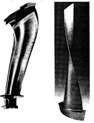
The efficiency of turbine stages can be increased by optimisation of blading systems, including classical optimisation of stator and rotor blade numbers and stagger angles, as well as optimisation of blade sections (profiles) and 3D blade stacking lines. The possible large number of shape parameters of 3D turbine blading requires efficient optimisation techniques. The figure below shows the blade rim of efficient „compound lean” nozzles for an HP turbine stage of Alstom as well as a view on the stator blade „sweep back” and rotor blade twist for an exit LP turbine stage, also of Alstom.
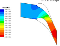
An HP stator with compound leaned blades of Alstom
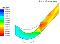
Stator and rotor blades for an exit LP turbine stage of Alstom
The code Opti_turb implements an idea of direct constraint optimisation, minimising the objective function - enthalpy losses of the turbine stage (stage group). The current value of the objective function is found from post-processing of 3D RANS computations in a solver FlowER (Yershov, Rusanov). In order to secure global flow conditions, there are also constraints imposed on the mass flow rate, exit swirl angle, average reaction, reaction at tip and root, stresses in the metal. Stresses are calculated from the code WYKA (Kaczorowski, Koronowicz). The exit swirl angle, reactions and stresses are not allowed to assume values beyond certain ranges of variation, meaning that if they fall beyond these ranges, an infinity is prescribed as a current value of the objective function. The penalty function is imposed on the mass flow rate if it falls beyond the assumed, usually very narrow, range of variation, with a penalty weight coefficient prescribed in a way that the objective function sharply rises to infinity with an increasing distance from the lower or upper limits of the assumed range of variation.
A number of deterministic (direct search, simplex), stochastic (genetic algorithms, simulated annealing) or hybrid stochastic-deterministic methods are used. Among new methods are two hybrid stochastic-deterministic algorithms. The first method is a combination of a genetic algorithm and simplex method of Nelder-Mead. The other method is a combination of a direct search method of Hooke-Jeeves and simulated annealing. These methods are effective both for single-extremum and multimodal objective functions.
There are two methods of parametrisation of the blade profile. They make use of a set of circle arcs and rational Bezier functions. As shown in the paper these methods allow efficient optimisation of turbomachinery blading systems.
Multipoint optimisation of 3D blading in an LP turbine stage group
The flow efficiency of a group of two LP exit stages of a 50 MW turbine operating over a wide range of load is increased by means of optimisation of 3D blade stacking lines. A combination of linear and compound sweep and lean is added to the blade design to obtain new 3D stacking lines of stator blades.
The objective function was decreased by 1.8%. Most of efficiency gains come from optimisation of the second (exit) stage. For example, the efficiency of the second stage for nominal operating conditions was increased by 2.4%, for low load by 5.5%.
In the investigated case, the combination of stator blade sweep and lean leads to a reduction of the spanwise gradient of reaction, which in turn leads to a reduction of load of stator passages at the root and consequently to a decrease of flow losses in the boundary layers, in the trailing edge region and in the shock wave region. This is also accompanied by a reduced risk of appearance of an inlet shock wave in the rotor. The load in the rotor is increased at the root with a largely reduced extension of the separation region there. One can also observe the decreased endwall and tip leakage losses. As a result of optimisation, the stage group efficiency increases in the entire investigated range of load with the largest efficiency gains in the region of low and nominal load.
Change of the optimised parameters in stages 1-2
|
Optimised parameter |
Its change |
|
|
Stage 1 |
Stage 2 |
|
|
stator stagger angle1 [°] |
0,5 |
0,2 |
|
rotor stagger angle1 [°] |
0,2 |
-3,7 |
|
stator linear sweep angle2 [°] |
0,0 |
1,5 |
|
stator linear lean angle3 [°] |
-4,9 |
6,4 |
|
stator axial sweep rate at tip2 Δx/l (Δy=3Δx) |
-0,08 |
-0,14 |
|
stator compound lean rate at root3 Δx/l (Δy=3Δx) |
0,00 |
-0,06 |
1 positive value of stagger angle increment opens throats, negative value closes throats;
2 positive value when the swept stator blade is protruded forward (downstream) at the tip;
3 positive value when the leaned blade is protruded with rotation of the moving blades at the root.
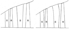
Original (left) and final (right) geometry of the stage group in meridional view.
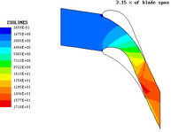
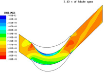
Mach number contours in the second-stage stator (left) and rotor (right) at the root for original (top) and optimised (bottom) geometry for the exit volumetric flow rate of 800 m3/s.
Optimisation of blade profiles in a low-load HP turbine stage
Optimisation of stator and rotor profiles (PLK and R2 profiles) was carried out for a low-reaction high-pressure (HP) stage of a 200 MW turbine using the combination of the Hooke-Jeeves method and simulated annealing.
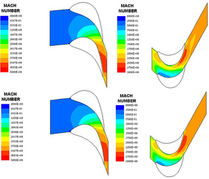
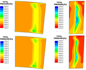
The objective function was decreased by 0.8%, which seems to be quite a considerable improvement. Mach number contours presented in mid-span blade-to-blade sections exhibit an improved expansion in the modified rotor cascade. Total pressure contours at the cascade exit sections indicate a reduction in the intensity of endwall flows, especially in the optimised rotor cascade, which becomes more aft-loaded. Thus, optimisation of the profile shape leads to the improvements both in 2D and 3D flow through the turbine cascades.
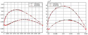
Original and modified geometry of the stator (left) and rotor blades (right)
Mach number contours in the stator (left) and rotor (right) at the mid-span:
original geometry (top), modified geometry (bottom)
Total pressure contours downstream of the stator (left) and rotor (right):
original geometry (top), modified geometry (bottom)
