Laboratory resources
We have a broad laboratory background allowing us to do our work in a modern, decent manner. We have four tunnels at our disposal.
- Transonic Wind Tunnel (vacuum, open loop type, up to Ma=2.5 for 20 seconds with throat of 100 cm2),
- Transonic Turbine and Compressor Cascade (almost ready, currently being in the process of launching),
- Subsonic Wind Tunnel (closed loop, extremely low turbulence level, up to 90 m/s with throat of 0.25 m2),
- Aerodynamic Tunnel for Wind Turbine Research (open loop, up to 40 m/s with cross section of 4 m2).
A brief on each of them is given hereafter, yet if you would like to get a deeper insight on any of them, do not hesitate to contact us.
Transonic Wind Tunnel
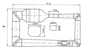
Built at the turn of the eighties and the nineties, benefiting from constant upgrades and care, still modern and in constant use. Launched in the nineties by a young after-graduate (who happens to be the head of the department and one of the world’s most influential scientists in the field today), today still doing high quality research. It is a vacuum driven Eiffel type tunnel whose scheme is given in Figure 1.
Figure 1 Scheme of the transonic wind tunnel
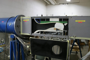
The actual view of the tunnel is given in Figure 2.
Figure 2 Test section of the transonic tunnel
The test section is rectangular in cross section, 100 mm in depth (spanwise) and 350 mm high. The length of the section is 1800 mm. The tunnel can produce a flow with Mach number reaching from Ma=0.1 to Ma = 2.5. The time of stationary conditions is not less than 20 seconds. It is an intermittent working regime tunnel, the time between the flows is approximately 5 minutes (it is the time necessary to evacuate the vacuum tanks, making the tunnel ready for the next run).
Transonic Turbine and Compressor Cascade
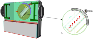
The latest tunnel in our laboratory, still in the launching stage. The design is given in Figure 3.
Figure 3 The cascade tunnel
It is be propelled by the same vacuum tanks that run the transonic wind tunnel. With the measurement section depth of 100 mm and 600 mm diameter it allows for measurement of approximately 6 or 7 compressor and turbine profiles in a flow with periodic conditions.
Subsonic wind tunnel
Also a very mature tunnel that has undergone a major renovation (including a new propelling and control system) recently. Designed and built for the research of the phenomena associated with the laminar-turbulent boundary layer transition. The schematic of it is given in Figure 4.
Figure 4 Subsonic wind tunnel
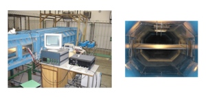
The actual image of the test section (both outside and inside) is given in Figure 5.
Figure 5 Subsonic wind tunnel test section
The tunnel has very low turbulence level (Tu < 0.08%) allowing for doing measurements of laminar-turbulent boundary layer transition. The achievable velocities reach from 0 to 90 m/s and the cross section of the main test section of 0.6 x 0.46 m allow for running tests of air vessels models.
Large, subsonic wind tunnel
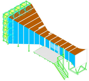
The one very different to the three previously described. It is an open wind tunnel with the test section cross section of 2 x 2 m. The visualization of it is given in Figure 6.
Figure 6 The large, open wind tunnel
The tunnel was designed for investigations on aerodynamics, operating characteristics and construction loading of wind turbines. The possible velocities reach up to 40 m/s. It is a continuous work regime tunnel. Apart for the ‘classical’ wind tunnel measurement transducers, it is equipped with dedicated apparatus for taking measurements specific to wind turbines:
- forces and torque, coupled with dynamic load system for measuring the operating characteristics of wind turbines (ω, P, M),
- velocity field in a chosen wind tunnel cross section,
- optical deformation measurement of the rotor components and tower,
- measurement of noise intensity and sources.
The last (but definitely not the least) technique from the list above is a very modern and extremely cool one. The ‘measurement of noise intensity and sources’ is an acoustic camera, a system that consists of an optical camera and a matrix of microphones. The two, coupled mechanically, synchronised temporarily and conjugated in post-processing equations give us a map of acoustic pressure in a reference system of optical photograph. (I have always wanted to use ‘coupled’, ‘synchronised’ and ‘conjugated’ in a single sentence). The apparatus yields a photograph that is coloured according to the intensity of the sound. The color scale is quantitative, suitable for further analysis. One of our results is given in Figure 7.
Figure 7 An opto-acoustic photograph of a working wind-turbine
The photograph depicts a Savonius-like wind turbine working on the roof of a building. After six months of working it started emitting very disturbing sound. Using the opto-acoustic photograph, the reason has been found. It turned out, that one of the bearings does need to be replaced ASAP.
Designed for wind turbines measurement, the tunnel has proven to be very suitable for measurements of façade elements, photovoltaic panels, MPPT systems dynamic characteristics when loaded with wind. We also have run an experiment on parachute characteristics in this tunnel. There is absolutely no problem to place a complete, rather large UAV in this tunnel and make a complete aerodynamical measurement campaign on it. We can measure the behaviour of the complete device including the forces and torques in all the phases of flight, complemented with visualisation of flow on the whole plating and in the surrounding of the object.


