Laser Micromachining Job-Shop
This system is multifunctional laser cutting system for micromachining of many different materials like: metal foils from copper, bronze, brass, aluminium, stainless steel and also materials like: ceramic, diamond and graphite. But according to its application, this system was designed especially for producing metal stencils in stainless steel foils used for applying solder paste during PCB manufacturing process in SMT technology. Thicknesses of these foils are varied between 80-200 µm), which depends on pads dimensions (the smaller pad the thicker metal foil is used). This system is based on new generation DPSS Nd:YAG laser (l=532 nm) which generates laser beam with average output power of 12 W. This allow to cut metal foils with thicknesses amount to even 0,5 mm.
System for micromachining was successfully used in applications listed below:
- Drilling holes and cutting patterns in metal foils,
- Cutting patterns in thin graphite and ceramic layers,
- Correction of the thin-layered and thick-layered resistors (circuit patterns directly on PCB),
- Cutting gap masks in brass foils used in calibration of thermo-detectors,
- Drilling a micro-nozzles in heads of precise tap (diameter of a nozzle - 60 µm).
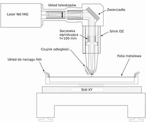
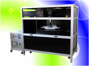
On Fig. 1 a schema of laser system for micromachining of the materials is presented. The real view of the system is presented on Fig. 2. This system consist of two major elements: ND:YAG laser and XY table. Nd:YAG laser is DPSS pulse Nd:YAG laser (f=10 kHz, P=12 W), which consisted of two Nd:YAG crystals – first one is for producing good quality laser beam with Gausian profile, and the second one is for amplification of the laser beam. Both of the crystals are pumped using IR diode lasers.
Schema of laser system for micromachining ULMM-1
A real view of the laser micromachinig system ULMM-1
The major parameters of the laser system for micromachining of the materials are:
- Spot diameter – 10 µm,
- Working area: 60 x 60 cm,
- Cutting speed: 5 cm/s,
- Repeatability: 1 µm,
- Precision through all working area of XY table: 4 µm,
- Optical system for autofocusing,
- Minimal pad dimension: 30 µm,
- Average elements cutting speed: 2 pads/s,
- Available cutting metal foils up to 500 µm of thickness.
XY table is driven by planar-type motor characterized by very high acceleration. This provide a homogeneous quality of laser cutting through all working area. The laser system for micromachining is assembled also with many specialized subsystems, such as laser spot observation and inspection system or automatic focusing system with capacity distance measurement feedback control.
Laser spot observation and inspection system consist of micro CCD camera (2 mln pix) connected to computer PCI video card. Inspection is carrying out through dedicated computer software with image recognition algorithm included. It monitor a laser spot shape online. This system is also used for controlling shape of pilot laser spot (diode red laser beam), which is used as a reference point for distance between laser head and metal foil. Any misplacing of the metal foil under the laser head is resulted in position changes of the red laser spot on the camera CCD chip.
Automatic focusing system consisted of another CCD camera (distance measuring system on Fig. 1), which is mounted on the laser head, and Z-planar motor. This is feedback system, where laser beam position displacement on CCD chip is translated into focusing lens movement, which is inside Z-planar motor. This keeps a constant distance between laser head (focusing lens) and cutting metal foil.
To take advantage of our offer, please contact dr. M. Kocik: kocik@imp.gda.pl


